Why this is here
This case study is on the portfolio for a specific reason that has nothing to do with the carillon. It’s the only entry in my portfolio that’s pure field diagnostics — finding what broke on a piece of hardware I didn’t design, with no schematic, in a building that wasn’t built for repair work, on a system that needed to keep working for a community that wasn’t going to wait for me to learn. EN-59 is design. NeuroMatrix is verification. Ensemble is software. The carillon is what happens when something that’s been working for forty years stops working, and somebody has to figure out why with whatever’s in their toolbox.
If you’re reading this and you’ve ever inherited a system you didn’t build that broke in a way nobody documented — you know exactly what shape this story is.
The system, and what broke
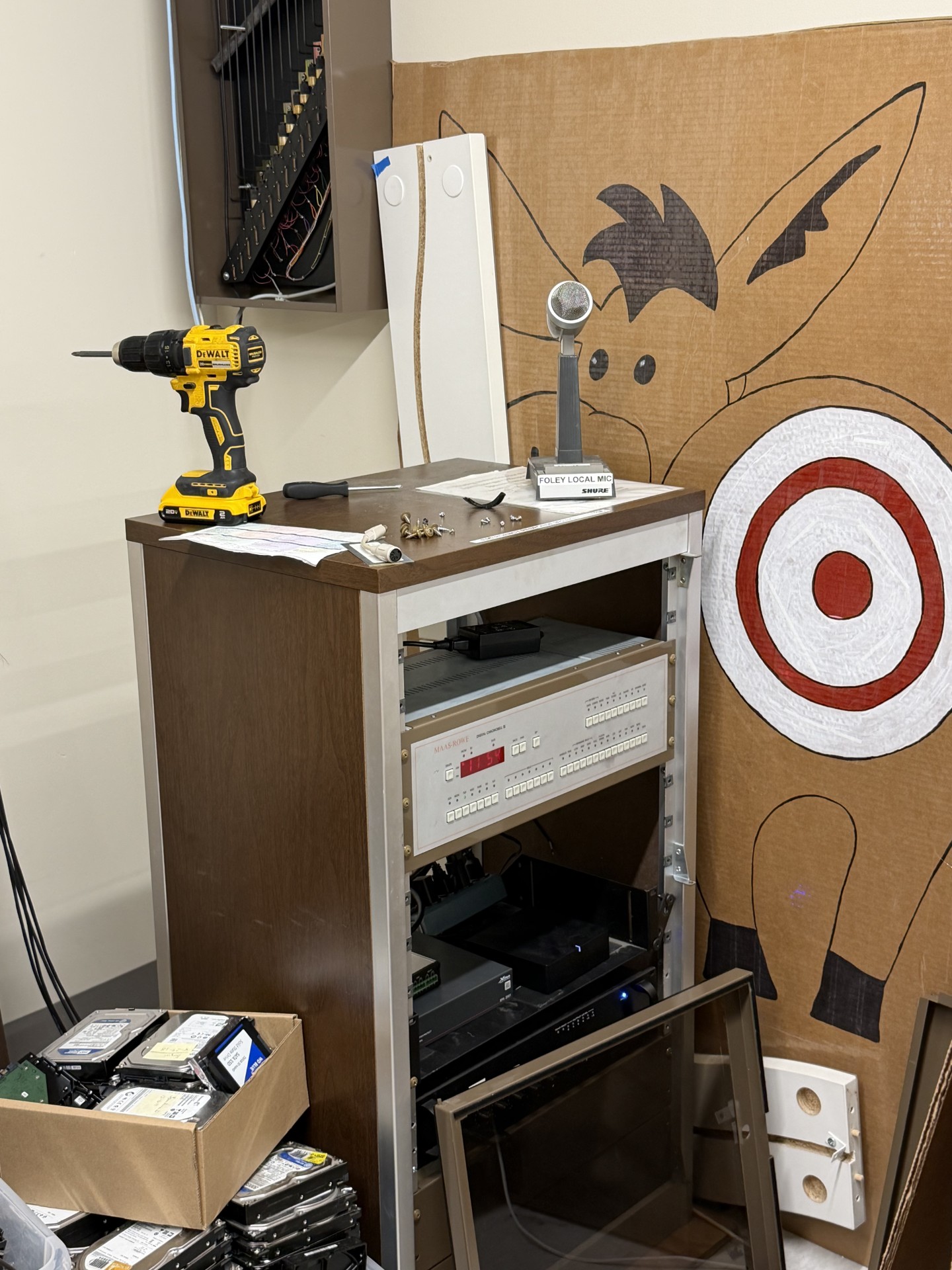
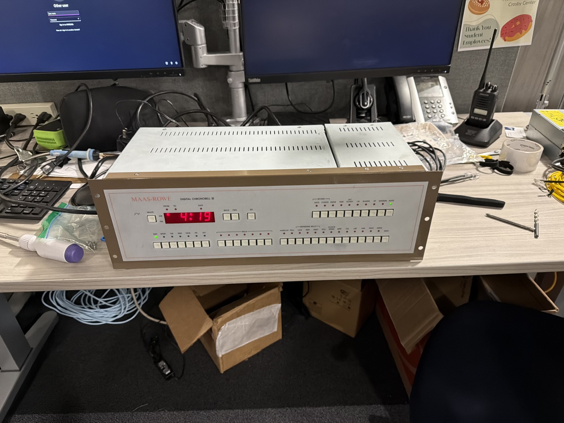
A carillon controller is the digital brain of a bell tower. It takes time-of-day signals, scheduled musical programs, and manual commands, and translates them into pulses sent to bell actuators — solenoids or motorized strikers mounted on each bell that physically hit the bell to produce the note. The Chronobell III is a particular model from Maas-Rowe (a manufacturer that’s still around, but the III is many generations obsolete and the documentation is essentially lost). It runs the kind of architecture that 1970s hybrid analog/digital electronics specialized in: TTL logic for sequencing and program memory, analog drivers for the actuator outputs, a chassis power supply that fed both the logic and the actuator drive rails from one transformer-rectifier-regulator chain.
The fault was straightforward to observe and unrecoverable from the original parts. The bells had stopped ringing. The carillon was powered on at the wall, fans were running, indicator lamps were lit — but no actuator output, no logic activity on the front-panel indicators, and the unit was effectively dead. Two rails carried the load: a 36 V rail for the actuator drivers (high enough to give the solenoids the punch they need to strike a bell hard enough to be heard from a tower) and a 5 V logic rail for the TTL. Both were gone. The onboard linear regulators that produced them were unrecoverable — one was visibly distressed (discoloration around the case), the other read short across input-to-ground when I pulled it.
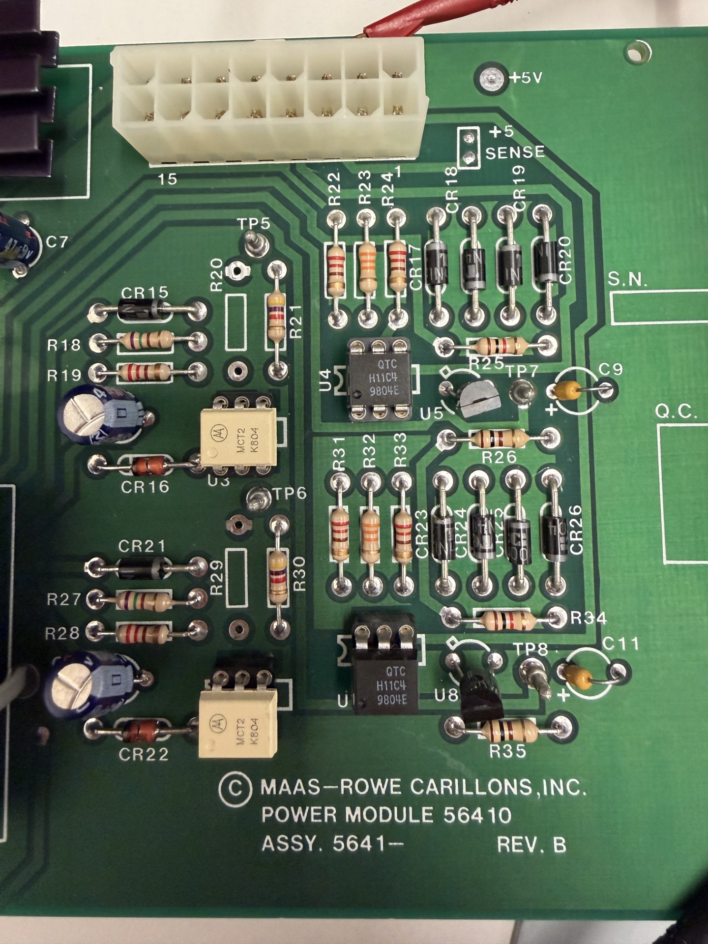
This is where “no schematic” became the problem. Maas-Rowe’s documentation for the Chronobell III isn’t on the internet. There’s no archive at the university. Maas-Rowe support, when contacted, did not have records for a unit this old. The board itself had silkscreened reference designators (R47, C12, that kind of thing) but no schematic diagram to map them to. Whatever was happening on that board, I was going to have to figure out from the board.
Reverse-engineering the power section
The diagnostic approach when you have no schematic is the same approach every electronics technician has used since the 1940s: trace the board with your eyes, your hands, and a multimeter. The board tells you what it is if you ask it patiently.
The procedure I worked through:
Identify the rails. Probe every large electrolytic capacitor — they sit on the rails they smooth, so a capacitor’s terminals tell you what voltage that node is supposed to be at. A 4700 µF / 50 V cap is on the 36 V rail; a 2200 µF / 16 V cap is on the 5 V rail. The voltage rating constrains the rail; the position on the board constrains the topology.
Find the regulators. Trace from the rectified-but-unregulated DC (the big caps right after the rectifier diodes) to the regulator’s input pin, and from the regulator’s output pin back to the smaller filter caps and load distribution. The 5 V regulator was a 7805-family linear part in a TO-220 package on a heatsink; the 36 V regulator was a custom linear discrete design (transistor + zener reference + emitter follower) because no off-the-shelf 7836 exists.
Confirm the rail loads. Once I knew where each rail entered the digital and analog sections, I could measure the load impedance with the regulators removed and the board powered down. The 5 V rail showed reasonable static load resistance to ground — no shorted decoupling cap, no obvious downstream failure. The 36 V rail looked the same. Good news: the failure was confined to the regulators themselves, not to whatever they were powering.
Verify the rectifier and transformer stages. With the board powered carefully (current-limited bench supply, low voltage to confirm the rectifier and smoothing caps were intact), the unregulated DC at the regulator inputs looked correct — the transformer was fine, the bridge rectifier was fine. The failure was specifically the regulators.
The reverse-engineering wasn’t dramatic. There was no “aha” moment. It was an afternoon of probing and writing notes on a clipboard, and at the end of it I had a one-page sketch of the power section that was good enough to plan a repair around.
The repair
The decision tree at this point is: rebuild the original regulators, replace them with modern equivalents, or feed the board the rails it needs from somewhere else. Each has tradeoffs.
Rebuilding the originals would have preserved authenticity, but it required source parts I’d have to special-order (the 36 V section used a TO-3 transistor I couldn’t find at any normal supplier), and it would have produced a repair that was as fragile as the original.
Replacing with modern linear regulators (LM317 in current-mode for the 36 V, LM7805 for the 5 V) would have been close in spirit to the original, but the linear topology wastes power as heat, and 36 V × actuator current is non-trivial heat for a 24/7 fixture in a building with limited cooling. The original regulators may well have died for exactly this reason.
Feeding the rails from external DC adapters was the cleanest answer, and the one I chose. A 36 V switching power adapter (the kind that ships with industrial actuator equipment) feeds the 36 V rail directly at the input of where the old regulator’s output used to land. A 5 V switching adapter does the same for the 5 V logic rail. Both adapters live outside the chassis; the old regulator footprints are bypassed entirely, with the wiring routed cleanly to the rail nodes I’d identified during reverse-engineering. Switching adapters in 2024 cost less, run cooler, and have better load regulation than the 1970s linear designs they replaced, and they can be swapped in 30 seconds when one eventually dies.
The repair is in the spirit of what would a working version of this system look like today rather than how do I make the original work again. For a 50-year-old fixture in a community building, that’s the right tradeoff. The bells need to ring; nobody cares whether the regulator is the original part.
The actuators, briefly
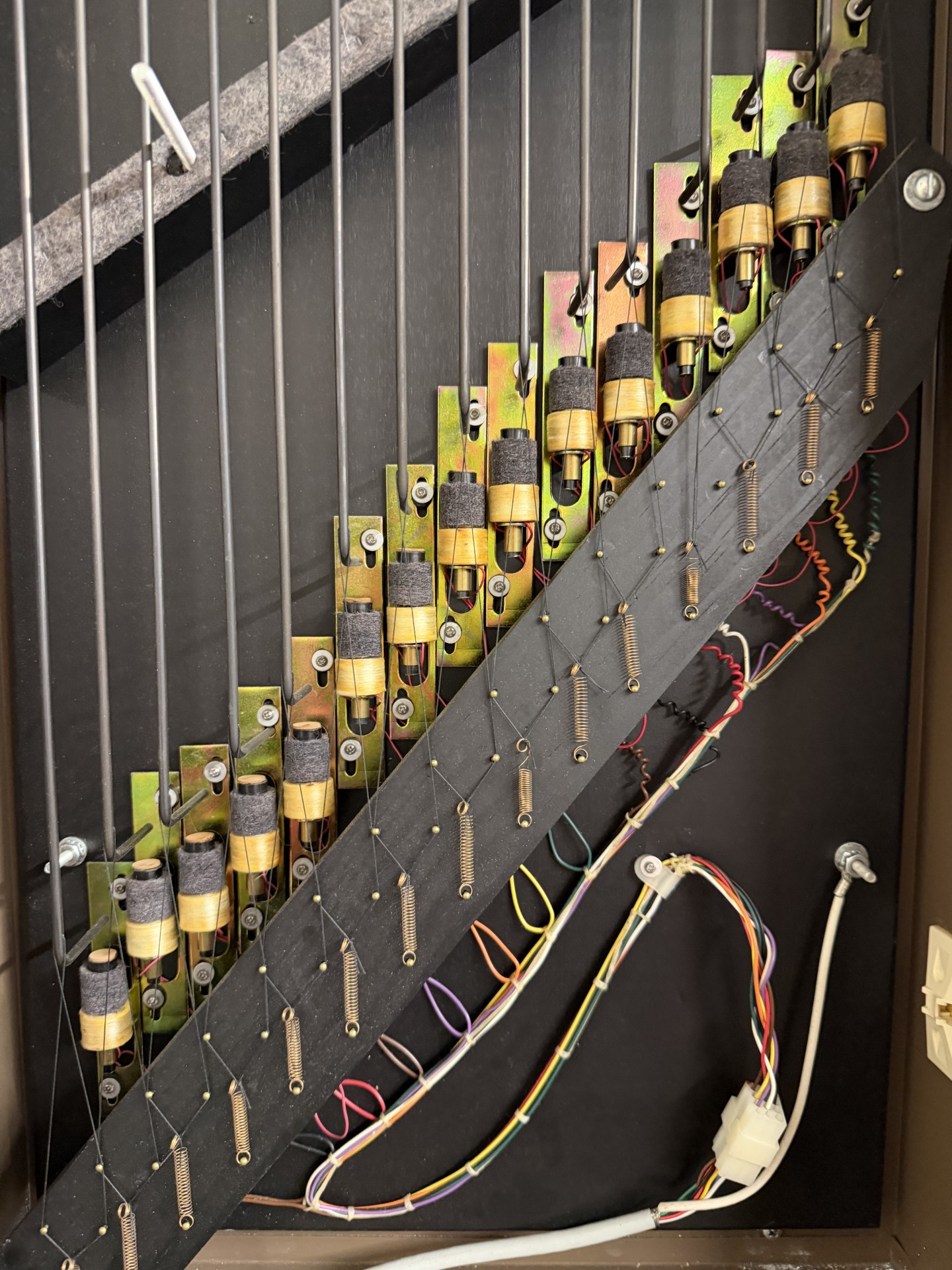
The other half of the system is the actuators — the mechanisms that physically strike each bell. The Chronobell III drives them through what are effectively very large MOSFET (or, in this vintage, bipolar Darlington) switches: a logic pulse from the controller turns the switch on for a few tens of milliseconds, the switch dumps 36 V into the actuator’s solenoid winding, the solenoid yanks a striker into the bell. A bell makes its sound because something hits it hard; the carillon’s job is to coordinate which somethings hit which bells when.
I didn’t repair any actuators on this round. They were fine — the actuator hardware in a bell tower is mechanically simple and built to outlive everything around it. But it’s worth showing them, because they’re the load the 36 V rail was driving, and they’re the reason the rail needs to be 36 V rather than something more polite. Bell strikers need current, and 36 V into a low-impedance solenoid winding is what you pay to get a respectable strike.
What I learned from this
A few things, none of which I learned in a course:
Reverse-engineering is mostly patience. There’s a temptation to look for the clever shortcut — the schematic on the internet, the application note from the manufacturer, the one person on a forum who’s seen this board before. Most of the time, there isn’t one. The board is the documentation. Probing it methodically, writing down what you find, and resisting the urge to guess is the actual work. It is slower than you want and faster than you’d think.
The right repair is often not the original design. I went into this work expecting to rebuild what was there. Halfway through reverse-engineering the power section, I realized the original design’s failure mode — linear regulators dissipating tens of watts as heat in a chassis with limited cooling — was predictable and recurrent. Rebuilding the original would have set up the next failure on a timer. Replacing the failed approach with the modern approach (switching adapters, external, cheap, hot-swappable) treated the actual problem rather than the symptom. Respect for the original system doesn’t mean reproducing its mistakes.
Field repair is end-to-end engineering with no abstraction layer. When EN-59 fails in the field, somebody who isn’t me is going to have to debug it. That somebody is going to have a multimeter and a clipboard and no documentation that matches what’s actually in front of them, because the documentation never does. Doing the carillon work made me a better designer of the things I design from scratch, because I now have a more visceral sense of what it’s like to be on the other end of an undocumented hardware problem at 9 PM with a deadline. Designing for field-repairability isn’t a nice-to-have; it’s the only reason anyone will be able to keep your work running after you’re gone.
Old hardware deserves the same engineering respect as new hardware. The Chronobell III is, by every modern measure, obsolete. It’s also a piece of working community infrastructure that’s been performing its job for half a century. The carillon’s continued operation matters to the people who hear it. Treating the unit as worth repairing, rather than worth replacing with whatever the modern equivalent costs, isn’t just sentimentality — it’s a reasonable engineering position. The carbon and capital cost of replacing functional 50-year-old hardware is much higher than the cost of repairing it. I wrote almost the same sentence in the NCS Cluster writeup. I keep encountering versions of the same truth.
If you have a piece of old hardware you’ve inherited that broke and nobody can fix it — try the reverse-engineering approach before you give up on the unit. Most failures cluster around a small number of failure modes (rails, electrolytics, switches, connectors) and most of them can be diagnosed with a multimeter and an afternoon. The bells of Gonzaga ring again because of an afternoon with a multimeter. Worse outcomes have come from more expensive investigations. Email me if you want to compare notes.