Why this writeup exists
A coffee machine FSM is the kind of problem you get in a sophomore digital design course. It’s not novel and it doesn’t need a portfolio entry. So why is it here?
Because the verification methodology is what I want to talk about, and a small problem is the right place to demonstrate it. Real industry verification — the kind done by Intel CPU validation engineers, AMD DV teams, anyone shipping silicon — uses constrained-random stimulus, functional coverage, and reference-model scoreboards. Coursework usually doesn’t. I treated this assignment as practice for the methodology, not the result.
If you’re reading this case study, you’re probably one of two audiences: someone hiring for a verification or digital-design role and wondering whether I know what UVM testbench architecture actually means, or someone curious about how to approach class projects when you want them to count for more than the grade. Either way, this is a small piece of work and I’ll keep the writeup short.
What it does
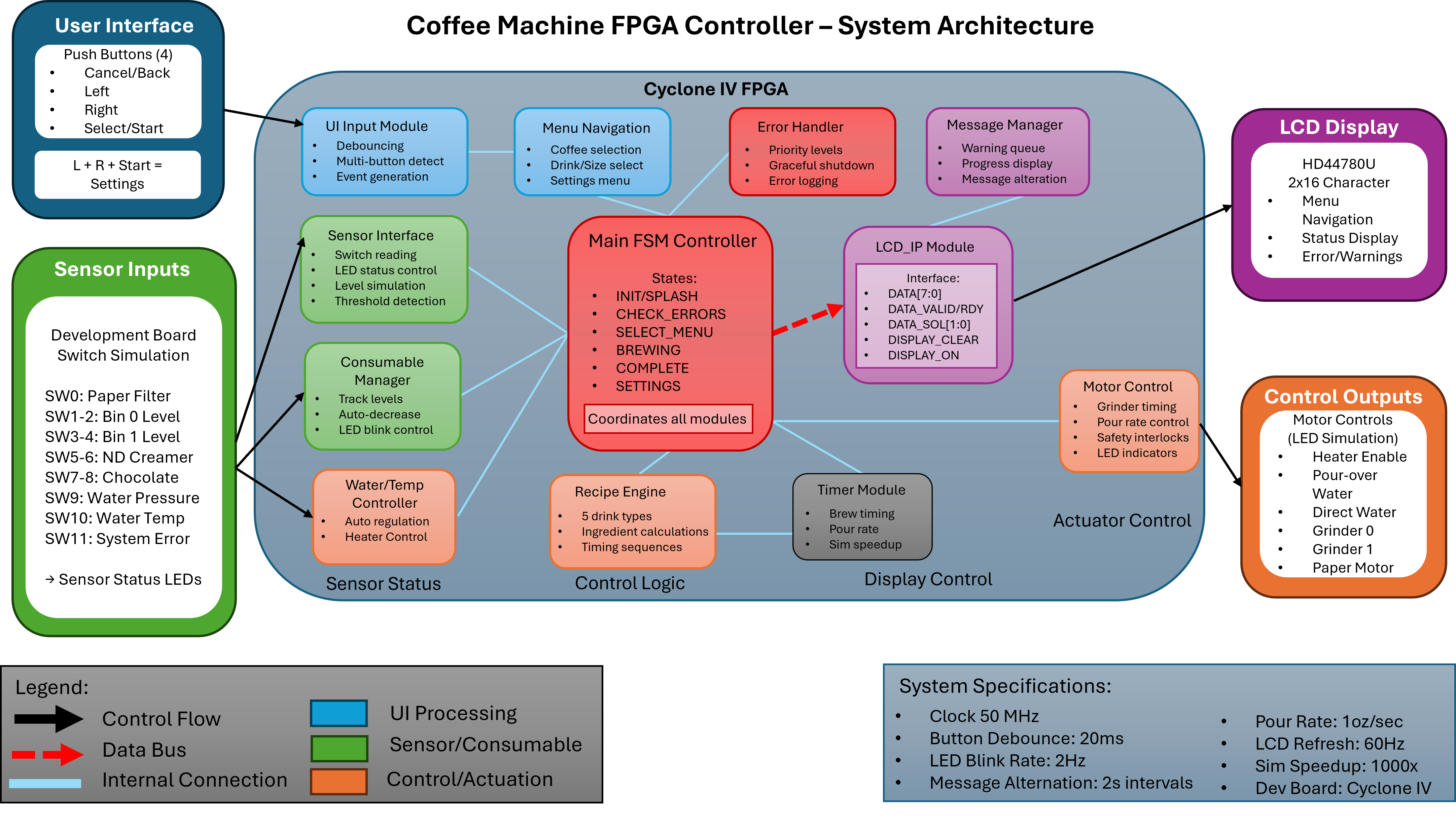
The system models a vending coffee machine. Inputs:
- Coin slot — accepts denominations of 5, 10, and 25 (generic value units; the design doesn’t care whether they’re cents, tokens, or arcade credits)
- Selection buttons — 5 drinks, each with its own price, ingredient set, and dispensing sequence
- Reset / cancel
- System clock and synchronous reset
Outputs:
- Drink dispense signal plus the per-ingredient activation lines (water, milk, coffee grounds, sugar, etc.) that control which subsystems run for how long
- Change return with denomination
- LCD display showing machine state (idle, accepting payment, current total, dispensing, error)
- Error indication for invalid states (drink unavailable, jam, overpayment with no change available)
The controller is the FSM coordinating these. The implementation is hierarchical: a top-level FSM handles overall machine state (idle → accepting → dispensing → returning change → idle), with sub-FSMs for coin handling, drink selection, dispensing sequencing, and error recovery.
The hierarchy across ~14 modules breaks down roughly as: a top-level coordinator holding the master state, a coin handler debouncing the slot input and accumulating denominations, a drink selector latching button presses and checking price against accumulated value, a dispensing sequencer that walks through the per-drink ingredient activation sequence (this is the module that varies the most by drink — espresso runs the grinder and pump for one timing, hot chocolate runs the milk heater for a different timing), a change returner running a greedy denomination algorithm, an error handler detecting invalid states, an LCD driver that interfaces with the display IP, plus infrastructure (clock divider, reset synchronizer, button debouncers, an inter-module arbiter).
The variable-time-per-drink dispensing is the part that turned out to actually be tricky. Different drinks need different ingredients activated for different durations, in different orders, and the FPGA’s deterministic timing has to line up with what the spec says happens in real-world coffee-machine seconds. That’s where most of the bugs lived.
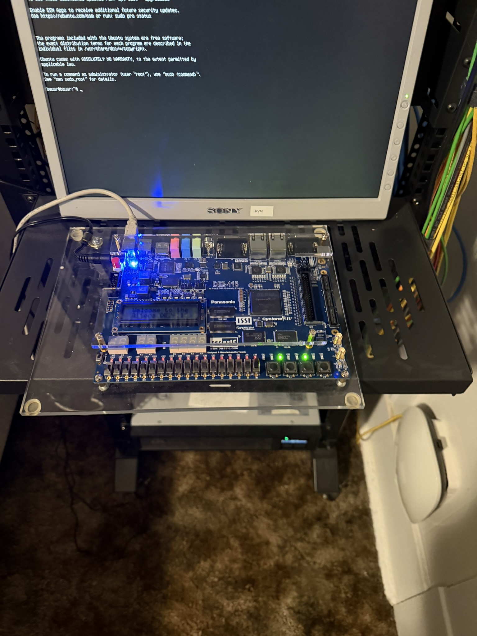
It’s a simple system. The point isn’t the system.
The verification approach
This is the part worth describing.
The naive approach to verifying a coursework FSM: write a Verilog testbench that drives the inputs through a sequence of cases the spec mentions, checks the outputs match expected values, and prints pass/fail. Maybe 100 lines of testbench for 200 lines of design. Pass the assignment, move on.
The approach I took instead, modeled after how production verification environments are built:
A behavioral reference model, written in SystemVerilog from the natural-language spec — not by looking at my own implementation. The reference model is itself an FSM, but written for clarity over efficiency: maximally explicit transitions, no shared state across what should be independent functional blocks, no optimization. The point is to encode what the spec says the machine does, in a form independent enough from the design that bugs in one are unlikely to mirror bugs in the other.
A constrained-random stimulus generator that produces sequences of inputs respecting the rules of the world (you can’t insert a half-coin; you can’t press two drink buttons simultaneously, depending on the spec; resets happen at any time). The randomness exercises state transitions and edge cases that a directed test won’t hit by accident.
A scoreboard that runs the reference model in parallel with the design-under-test, on the same stimulus stream, and flags any cycle where their outputs disagree. This is the heart of the methodology — the testbench knows what the design should do without me having to write down each expected value.
Functional coverage points for the state transitions and corner-case conditions that should be exercised. The simulation reports coverage at the end of each run: which states were entered, which transitions taken, which error conditions reached. Coverage below 100% means stimulus isn’t exercising enough; coverage at 100% means every state was visited, which is a weaker statement than “the design is correct” but a necessary one.
Assertions inline in the design and at module boundaries —
assert propertystatements for invariants the design must satisfy (e.g. “dispense and change-return are never asserted simultaneously,” “drink output is always preceded by sufficient payment within the same activation”). These catch bugs at the moment of violation, not at the output edge.
The whole environment is roughly the shape of a UVM testbench without the full UVM class library — agents driving stimulus, a monitor watching outputs, a scoreboard comparing against the reference, coverage collection running throughout. It’s not literally UVM (UVM has more ceremony than a coursework project needs), but the architecture is the same architecture a UVM environment would have.
What bugs this caught
The interesting outcome: the reference-model approach caught real bugs that directed tests would not have found. The bugs clustered around three places, all of which are familiar to anyone who’s done digital design.
Clock-timing bugs. The main FSM ran on the system clock; the LCD IP needed a much slower clock for its serial interface; the debouncers needed something in between. Getting the dividers right — and getting signals to cross domains cleanly — was where the first round of bugs lived. The reference model assumed an idealized “every input is sampled cleanly on the rising edge” world; the design had to actually deal with metastability and propagation delays. The scoreboard would flag a cycle where the reference said the machine had moved to DISPENSING and the design was still in ACCEPTING, and the cause would turn out to be a coin signal that had crossed the debouncer’s clock domain one cycle later than expected. The fix was usually a synchronizer flop or an extra cycle of latency in the reference model to match — and importantly, choosing which one was correct was the engineering decision, not a guess.
LCD display IP integration. The LCD’s HD44780-style controller has its own timing requirements — RS and E strobes, instruction-vs-data modes, busy-flag polling, a hard 37 µs delay between writes. The first version of the LCD driver violated these requirements under specific message sequences and the display would either show garbage or hang waiting for a busy flag that never came. The reference model didn’t model the LCD at all (the spec said “show machine state”; it didn’t say “show machine state via HD44780 timing”), so this class of bug had to be caught by directed tests against the IP datasheet and by assertion firings on the strobe timing. Some bugs are below the reference model’s abstraction layer, and you have to recognize when that’s true.
Variable per-drink dispensing timing. Espresso wants the grinder for 3 seconds, the pump for 25 seconds, then off. Hot chocolate skips the grinder entirely but runs the milk heater for 40 seconds, then the pump for 10. The dispensing sequencer needed a per-drink program — effectively a tiny lookup-table-driven sub-FSM where each drink’s “recipe” was a list of (subsystem, duration) tuples. The first version had a subtle off-by-one in the duration counter that made every step finish exactly one clock cycle early, which on a slow clock was hundreds of milliseconds per ingredient. In simulation against a step-by-step directed test, the duration counter looked fine. Against the reference model’s drink-program comparison — same recipe, same total time — the divergence was immediate and obvious. One cycle off the end of every step compounds across a recipe, and the constrained-random stimulus exercising different drink choices revealed it within the first few simulation runs.
Without the reference scoreboard, the dispensing-timing bug specifically would have either shipped in my submission or been caught by the TA grading. With it, the comparison surfaced the divergence immediately, before I’d even written a directed test for that case. That’s the entire argument for reference-model verification in one example.
Tools and choice notes
A few tooling decisions worth naming:
- ModelSim for simulation. Standard, available in the Gonzaga lab, supports the SystemVerilog features (assertions, covergroups, classes for stimulus generators) the methodology needs.
- SystemVerilog rather than Verilog for both design and testbench. The design didn’t need it; the testbench did —
class-based stimulus,assert property,covergroupare SV-only features. - FPGA deployment as the final validation step. Simulation says “the FSM does what the reference says it does”; FPGA deployment says “and it does it on real hardware at real clock rates with real button presses.” The clock-domain bugs above showed up in simulation because I had a clean reference model to compare against, but several of the LCD timing bugs only manifested on the board, where the real HD44780’s actual timing was tighter than the IP’s simulation model suggested.
- No formal verification. The design is small enough that formal would have been usable, and in hindsight I should have tried a model checker on the top-level FSM to prove safety properties exhaustively. I didn’t, because I didn’t know formal tools yet.
What I’d do differently
A short list, honestly:
- Use Verilator + cocotb instead of ModelSim. Open-source toolchain, faster simulation, lets me write the testbench in Python which would have made the constrained-random stimulus generator easier to write and reuse.
- Add formal verification on the top-level FSM. As above — should have tried it, didn’t know to.
- Start with the reference model. I wrote the design first and the reference model second. Industrial practice often inverts this — write the executable spec first, develop against it. Doing it the other way around meant the reference model and the design had some entangled assumptions I had to consciously break.
- Model the LCD IP at the right abstraction level in the reference. The strict separation I drew — “the reference doesn’t model the LCD, that’s a directed-test problem” — was the easy choice, not necessarily the right one. A reference model that captured the LCD’s command sequence at a transaction level would have caught the integration bugs earlier. Knowing where to draw the abstraction line is itself a skill, and I drew it too tight on the first pass.
- Functional coverage closure. I hit ~85% functional coverage by the end of the project; closing the last 15% would have required custom stimulus to exercise specific corner cases. I didn’t, because it wasn’t required. Doing it would have been good practice.
Why this is on the portfolio
To answer the obvious question directly: a coffee machine FSM doesn’t belong on a portfolio if the portfolio is about the coffee machine. It belongs there if the portfolio is about the methodology I used. For someone evaluating whether I can do digital verification work — Intel-style CPU validation, AMD DV, anyone shipping silicon where DV is the bottleneck — this is a small but legitimate demonstration of UVM-shaped thinking on a real piece of SystemVerilog, deployed to real hardware, with bugs that were real enough to be embarrassing if they’d shipped.
If that’s why you’re reading: I have more recent work in NeuroMatrix’s validation pipeline that scales the same instincts up (cross-tier consistency tests as the scoreboard, behavioral models as the reference, constrained sweeps as the stimulus). The coffee machine was the first time I built this kind of environment from scratch. The pattern stuck.